
A de-energized power line that parallels an energized power line is subject to induced voltage and current from that energized line. Basically, the amount of induced current and voltage is influenced by the following:
- The voltage on the energized line. The higher the voltage on the energized line, the higher the induced voltage on the parallel line. This is because an energized conductor has an electric field around it, measured in volts per distance, e.g., kV/meter. The higher the voltage, the larger the electric field.
- The current flowing through the energized line. The more current in the energized line, the higher the induced voltage on the parallel line. This is because current flowing through a conductor creates a magnetic field around it. The higher the current, the larger the magnetic field (more lines of magnetic flux).
- The distance between the energized line and the parallel line. The closer they are together, the higher the induced voltage and current.
- The length (distance) that the lines parallel each other. The longer the distance, the higher the induced voltage and current.
An ungrounded conductor that parallels an energized line is in an electric field induction (capacitive coupling) situation, caused by the electric field around the energized line. At one time this was called electrostatic induction. The induced voltage can be extremely high, sometimes more than 10% of the voltage of the parallel energized line. Installing a ground on that unenergized conductor discharges that high voltage, but then it charges right back immediately.
Installing a second ground on that same conductor at a different location places that conductor into a magnetic field induction (transformer coupling) situation, caused by the magnetic field around the energized line. At one time this was called electromagnetic induction.
Once more than one grounded location is established on a conductor, current may flow through the earth between the grounds. This is called circulating current. It is caused by the induction from the nearby energized line. As more grounded locations are established on that same conductor, more paths of circulating current are created. There may be as many circulating current paths as there are grounded locations. This circulating current at each grounded location sets up voltage gradients in the earth around the place where the conductor is grounded. The voltage gradients consist of step potentials, touch potentials, and transferred touch potentials. See the sidebar for a definition of these potentials.
These differences of potential in the earth pose an electrical hazard to the workers on the ground who are in the voltage gradient zone. The hazard ranges from mild electric shock to fatal electrocution. This is why line crews measure the differences in potential in the earth at the worksite with a voltage meter referred to as a "step and touch kit."
One example of a product solution is the Step and Touch (SNT) instrument manufactured by Delta Computer Systems, Inc. of Battle Ground, Washington. The Delta tool monitors and alarms step and touch potential caused by ground potential rise. When used properly, the SNT can enhance the safety of transmission line crews. The SNT (see Figure 1) provides audible and visual alarm warnings if the probe voltage is in a dangerous range. Each voltage range has a distinct pattern of bright flashing LEDs and audible 80 dB(A) alert. The SNT also detects and warns of Lost Probe Connection and Low Battery.
Multiple line crews that are working at different locations on the same line (conductor) and measuring the step and touch voltage at their worksite may see that voltage change as a different crew installs or removes their own protective grounds. This is due to the fact that installing or removing grounds on the same conductor at one location changes the number of circulating current paths. This change may increase the potential hazard at other grounded locations along that conductor.
It is for this reason that when more than one line crew is working on the same conductor at different locations it is important that they communicate with each other prior to the installation or removal of protective grounds. Installing or removing a ground at one site may have a profound influence on the step and touch voltage at the remaining sites.
Sidebar:
STEP POTENTIAL: The voltage between the feet of a person standing near an energized grounded object. It is equal to the difference in voltage between two points at different distances from the grounded object (the ground electrode). For worker protection this distance is usually assumed to be about three feet, or the distance between a worker’s feet while in a walking configuration. A person could be at risk of injury during a fault simply by standing near the grounding point.
TOUCH POTENTIAL: The voltage between the energized object and the feet of a person in contact with the object. It is equal to the difference in voltage between the object (which is at a distance of 0 feet) and a point some distance away, usually assumed to be about three feet, or the distance a worker could touch an object while standing on the ground.
TRANSFERRED TOUCH POTENTIAL: The voltage between the energized object and the feet of a person standing on the ground while making contact with the energized object (the ground electrode) through a conductive medium such as the frame or winch line of a vehicle that has been bonded to the grounding electrode with a length of grounding cable. The same applies to a worker with no worksite protection who is contacting a conductor that is grounded at some remote distance. This voltage may be much higher than the “touch potential” due to the greater distance between the worker and the grounding electrode.
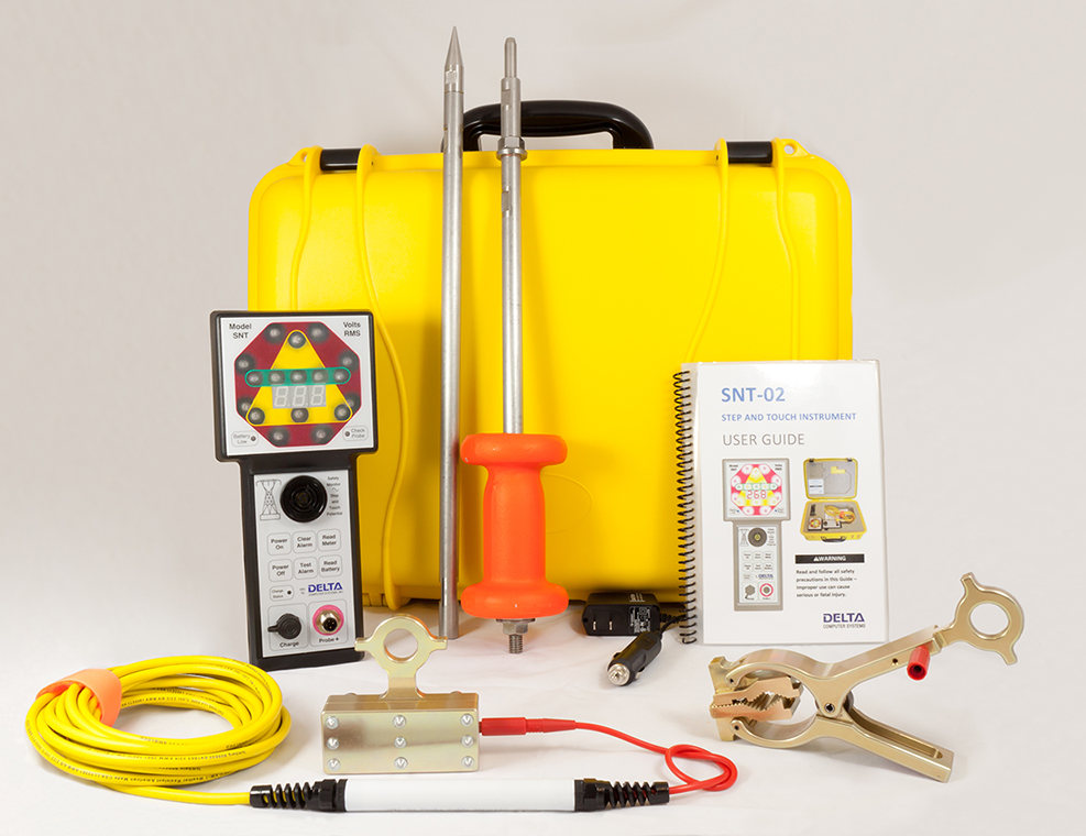
Figure 1