
A couple of weeks ago, I read a newspaper article about an accident that had happened to a line crew while working on a “de-energized” power line. A lineman had been severely injured when exposed to the line’s high voltage. Crew members stated they “thought the line was out of service.”
That statement — “they thought the line was out of service” — really grabbed me. After all, with modern technology and advanced safety awareness, why would a line crew think a circuit was out of service without taking the necessary steps to ensure it was indeed de-energized?
Nor is this a lone incident. You can find similar cases around the Web, including this one on the CDC’s site, which notes, “The decedent may have assumed the line was de-energized.”
Even one injury is too many, and this problem keeps recurring. Perhaps a brief look at bonding and grounding — the difference between them, our goals in doing it, how these goals are achieved, and especially the five bonding and grounding practices that will keep you alive — is in order. Because a little recap can go a long way in preventing pain and loss.
Bonding and Grounding Basics
The difference between “bonding” and “grounding” from a personal protective standpoint is this:
“Bonding” means connecting two or more conductive components in the work area together with another conductor, such as a length of wire or other conductive device. The goal of bonding is to remove potential (voltage) differences between the bonded objects. In other words, bonding puts things at the same potential. Since bonded components are at the same potential, there will be very little current flow between them. Thus, the bonding wire doesn’t have an ampacity requirement; it can be a small wire such as #9 or #6 copper or 1/0 soft-drawn all aluminum.
“Grounding,” on the other hand, means connecting a normally current-carrying conductor to earth or something that represents earth, such as a metallic structure anchored in the earth. Grounding provides a path to earth (ground) that has the ampacity (current) to carry fault current to earth in case the line is energized from its normal source, including in the event of human error. In doing so, grounding causes the isolating devices (fuses, relays, circuit breakers, etc.) to operate and de-energize the circuit in as short as time as possible. This means that the grounding cable does have an ampacity requirement; it must carry the fault current for the length of time that it takes to clear the circuit.
So, bonding has a voltage requirement while grounding has a current requirement. At a worksite, the bonding system must be connected to the grounding system to place all conductive components in the work area at the same potential. Once that is accomplished, an equipotential zone (EPZ) has been established.
Why We Bond and Ground a De-energized Power Line
Things would be easier and safer if bonding and grounding weren’t necessary. However, many factors can lead to the necessity. If you’re regularly conscious of only some of the contributing factors, a look over a full list might be beneficial.
- The line may still be energized. The normal source may have never been turned off, as in our introductory example.
- Human error. Somebody makes a mistake and energizes the line by closing isolating devices.
- Accidental contact. The conductor being worked on somehow makes contact with an energized conductor.
- Backfeed. This can occur from a generator, transformer, etc.
- Lightning.
- Testing.
- Equipment failure.
- INDUCTION. This can develop from factors such as nearby energized lines and wind storms.
I put INDUCTION in all caps because it has been my experience that induced voltages from nearby energized lines cause more injuries and fatalities to electrical workers every year in the USA than all other listed reasons combined.
Goals of Bonding and Grounding
Powerline workers should establish a worksite EPZ by connecting all conductive components, including the phase conductors, together with appropriately sized bonding and grounding cables. Now, as the above list illustrates, energization can happen at any time for a host of reasons. Thus, linemen must take steps to limit possible current flow through themselves in case of an energization (from any source) to less than 100 milliamps. Similarly, they must limit the voltage drop across the worker in case of an energization (from any source) to less than 50 volts.
Limiting the current through and the voltage drop across the lineman is accomplished by installing an appropriately sized cable in parallel with the worker from the point where the worker is making contact with the conductor to the point where the worker is making contact with the earth (ground). By doing this, a shunt has been placed around the lineman so that most of the current will flow through the shunt and a very small amount (if any) will go through the worker. Also, the shunt places the worker at the same potential as the conductor, thereby limiting the voltage drop across him or her.
The “Rules of Five That Will Keep You Alive”
Powerline maintenance may take place in a chaotic environment, and work can happen in the middle of the night when linemen are not at their most alert. Safety should be boiled down to its simplest, easiest to remember components. So, if a short list of brief precautions can help guide you through the grounding and bonding essentials, try this:
- Make sure you are on the right circuit.
- Make sure the circuit has been separated from all known sources.
- Test the circuit for absence of voltage with a voltage-detecting instrument that gives both a visual and audible signal.
- Bond all of the conductive components in the work area together.
- Ground the conductor to earth with grounding cables. Connect the bonding system and the grounding system together.
I wish I had a catchier acronym to offer than I.I.T.B.G., but that really is the order in which these five steps should be executed.
Staying Safe
Once a structure has been made safe for workers aloft by establishing an EPZ, any current that is in the phase conductors because they are energized (again, by any source) is going to flow to earth (ground) through the grounding cables. If there are any energized high voltage power lines on the same right-of-way as the one being worked on, there will be a voltage and current induced in the supposedly “dead” line. The amount of induced voltage and current depends on these few factors:
- The voltage of the parallel energized line. The higher the voltage of the energized line, the higher the amount of induced voltage on the “dead” line.
- The amount of current in the energized line. The higher the current (load) in the energized line, the higher the amount of voltage induced in the “dead” line.
- The distance between the “dead” line and the parallel energized line. The closer they are together, the higher the amount of induced voltage in the “dead” line.
- The distance (length) that the lines parallel each other. The greater the length, the higher the amount of induced voltage in the “dead” line.
Any current flowing from the grounded phase conductors to earth through the grounding cables establishes voltage gradients in the earth around the point where it enters the earth. These voltage gradients consist of step potentials, touch potentials, and transferred touch potentials.
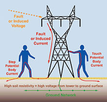 |
| Figure 1. The difference between step and touch potential body current. |
These step, touch, and transferred touch potentials are very difficult to control and are very hazardous to workers on the ground. If the voltage gradients are a result of induced currents from nearby energized lines, the amount my vary greatly during the day due to the loading of the nearby line, changing conditions of the soil around the grounding electrode (it may dry out during the day), and other factors.
Also, if more than one crew is working on the same conductor at different locations, induced current will flow through the earth from one grounding point to the other, establishing voltage gradients at each grounding point. This is called “circulating current.” The more locations the conductor is grounded, the more paths of circulating current are established, resulting in voltage gradients at each spot. Each grounding location should have the voltage gradient monitored with a voltmeter. Additionally, when a new grounded location is established, or when one is removed, the voltage gradients at the other grounded locations will change because the number of circulating current paths have changed. This is why line crews working on the same conductor at different locations should contact each other before installing or removing their grounds, because doing so will have an impact at their worksite.
For these and other reasons, line crews should constantly measure the voltage gradient in the earth at the grounding point with a meter that indicates what the potential difference between the grounding point and a location a certain distance (usually about 15 feet) from the grounding point. One of the most effective tools for this job is the Step and Touch instrument manufactured by Delta Computer Systems, Inc. of Battle Ground, Washington. The tool monitors and alarms step and touch potential caused by ground potential rise. The Step and Touch offers audible and visual alarm warnings when the probe detects dangerous voltage levels. Each voltage range has a distinct pattern of bright flashing LEDs (yellow from 101-499 volts, red at 500V and above) and an 80 dB(A) alarm. The tool also detects and warns of lost probe connections and low battery status. When used properly, an instrument like the Step and Touch can significantly enhance powerline crew safety.
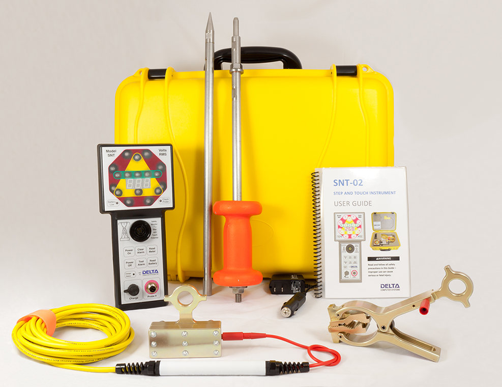 |
| Figure 2. Delta Computer’s Step and Touch instrument kit. |
“If it’s not grounded, it’s not dead.”
This is my least favorite grounding motto because it may lead you to believe that if it is grounded, it is dead. Trust me on this: If the conductor is energized due to induction, grounding does not kill it! Rather, at that point and at that point only, the conductor and earth have been placed at the same potential, meaning that the voltage difference between the two is essentially zero volts. However, at any other point between the conductor and earth, the potential difference will rise, and the farther the distance between the place where the conductor is connected to earth and the point where the conductor is contacted, the greater will be the voltage between the two.
Instead of this misleading maxim, let’s try something better able to protect you: “Don’t be shocked and astounded; make sure its bonded and grounded!”